OS : ubuntu
Render Backend: vtk 8.2
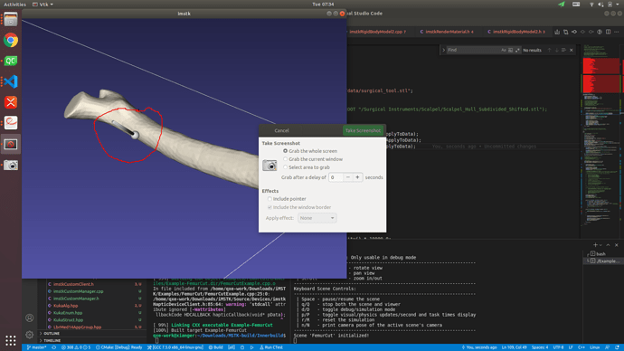
In my application , the movement of the end effector controls surgical tool object position, and orientation in the scene. the femur bone will be grinded by end effector, Meanwhile the software need to render the grinding process. how can i implement the effect(JUST LIKE PICTURE BELOW) base imstk library?
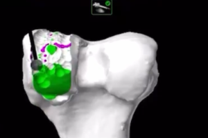
I had executed the example of “Example-Femurcut”, because my computer doesn’t support openhapstic, and i can’t run it correctly.
can you give me an example to indicate how to use the library to implement my effect?
Thanks a lot!
As mentioned before we do not support haptics on Linux. But FemurCut example is the correct example to look at if you have a haptic device (such as Phantom Omni) & are on windows.
You could modify the FemurCut example to use mouse controls, such as done in PbdTissueContactExample.
You could also integrate imstk in your own project with your own API for whatever device you have. What device are you wanting to use (ie how do you intend to control the tool)?
My device is a kuka robotic arm, and i want to implement this effect, picture below
Can i implement the effect with imstk?
I do not know about Kuka robot arms but brief googling would lead me to believe it has its own API you could download and use to query values (positions, orientations) and render forces. Such library could be used together with iMSTK by implementing your own imstkDeviceClient.
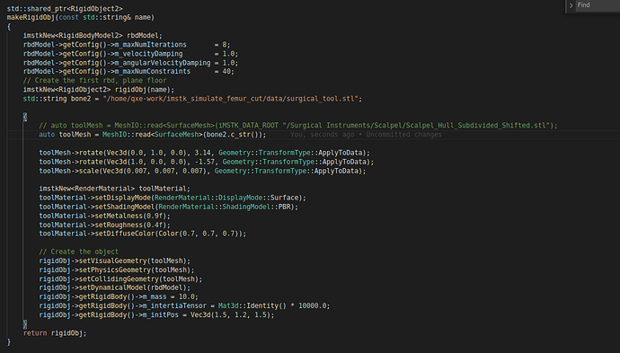
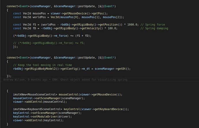
I want to custom surgical tool in Example-FemurCut. I create a tool object combined sphere and cylinder(picture below ). but i can’t move the tool object to collide with femur bone by mouse how can i adjust the parameters?
Looks good to me but you are using mousePos[2] which does not exist as mousePos is a 2d vector which gives X, Y coordinates on the screen (ranges 0 to 1 with origin at bottom left). Depending on how you want to map screen coordinates to 3d world coordinates, I would just put 0.0 for z of worldPos.
But I just swapped the bit of code you have for postUpdate function in to move the tool (and removed the controller + haptics bit) and it works fine. It just needs to be shifted over to make contact with the bone. The springs also a bit loose (you’d need to tune the 1000.0 and 100.0 on the spring and damper force).
Btw you can hit ‘d’ to go into debug mode and rotate/pan the camera to see where your tool may be at.
Commited these changes over on a yet to be merged branch of mine if you wanted to check them out https://gitlab.kitware.com/andrew.wilson/iMSTK/-/commit/5956a7a43006c186b73498d55d4654d7ac793af5
Thanks for you help, I found the reason why tool object can’t contact with bone, because the mousePos[2] is always 0.0, i change the z axes value to 0.1, the custom tool object can contact with bone now. I will arrange mine code and merge it to your branch. Thanks a lot.!
And There are another question confused me that is how can i integrate the imstk to my application, i copy the “imstk/build/install/include”, “imstk/build/install/lib” to my application, and link to a list of imstk .so format files to application, but the compile report undefined reference error for every function call in imstk. Is there exist some document to indicate the integration usage of imstk?
The bare minimum cmake to setup a c++ project via CMake and link to iMSTK looks like this:
cmake_minimum_required(VERSION 3.5.1)

project(MyProject)

# Gather all the source & header files in this directory
file(GLOB FILES *.cpp *.h)

# Find all of MyProject dependencies
find_package(iMSTK REQUIRED)

# Build an executable
add_executable(MyProject WIN32 ${FILES})

# Link libraries to executable (in modern target based cmake this links AND includes)
target_link_libraries(MyProject PUBLIC
	imstk::Common
	imstk::Geometry
	imstk::DataStructures
	imstk::Devices
	imstk::Filtering
	imstk::FilteringCore
	imstk::Materials
	imstk::Rendering
	imstk::Solvers
	imstk::DynamicalModels
	imstk::CollisionDetection
	imstk::CollisionHandling
	imstk::SceneEntities
	imstk::Scene
	imstk::SimulationManager
	imstk::Constraints
	imstk::Animation)
iMSTK_DIR must be given to cmake when buliding for find_package to find it. Where iMSTK_DIR = < your imstk build directory >/install/lib/cmake/iMSTK-5.0
We do have this example project that’s roughly up to date, serves as a nice learning material: https://gitlab.kitware.com/iMSTK/imstkexternalprojecttemplate Demonstrating the cmake build scripts for both a basic project and superbuild project.
Is imstk library support with qt default? If i want to integrate imstk into qt, can i directly change the vtkrenderwindow to vtkGenericOpenGLRenderWindow in <imstkVTKViewer.cpp> ?
We don’t provide any such integrations but I did toy with it today for a bit and got a working example on this branch. Just enables it in the build and provides an example, no API code. Might merge into imstk master soon. Untested on linux, branch likely to be rebased.
One of the issues with such a thing is that Qt and VTK use event based rendering, only rendering when an event notifying it to render is posted. This is great for UIs and such things that don’t render often but undesirable for highly interactive things like iMSTK and games where we’d prefer a more deterministic execution.
Luckily VTK allows one to make their own render calls allowing us to provide a more deterministic execution pipeline where we are always pushing frames (not event based). What I’ve done in my branch is thrown QApplication::processEvents before every render, this processes all Qt events before every render. The downside is that moving a slider, or doing anything in the UI that may cause many events would choke the simulation. So long as you aren’t fiddling with Qt whilst the simulation is running this would be useful. More useful would be to put the UI on a separate thread. The issues with this is any communication with the scene from UI may cause race conditions. One could start implementing synchronization mechanisms if they really wanted too.
What i think is separating imstk event loop into a single thread, and qt gui thread in another thread. If there are communications between imstk loop and gui thread. one could send message to another synchronously. In fact ,there are a few communications needed to send, In my view.
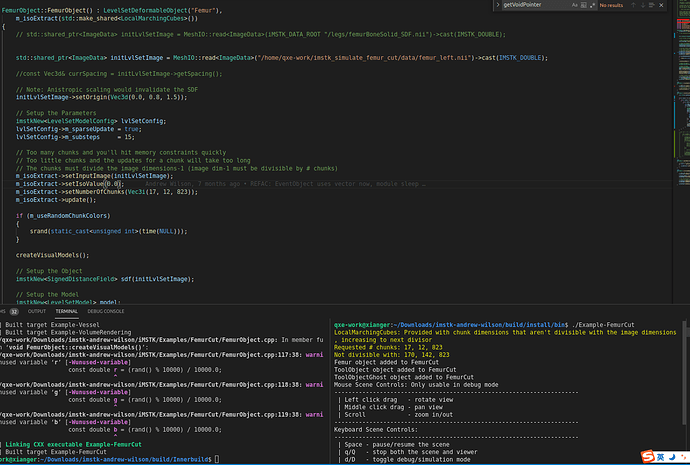
There are another question, can you help me? If i want to use mine nii data to replace the data used by Example-FemurCut. What parameters i should adjust?
The nii data there is a signed distance field (SDF). Used to initialize the levelset. The SDF is image of single scalar values that give the signed (negative inside, positive outside) nearest distance to the surface.
SDFs are expensive to compute, but you can do so once and store it as we have done here. We provide a filter called SurfaceMeshDistanceTransform which can produce an SDF image from an input triangle mesh. This triangle mesh needs to be closed and manifold.
You could write this image out using MeshIO::write(myImageData, "myLocation/myImageData.mhd");. I would suggest using mhd format instead of nii (mhd writes both a mhd and raw). This is because our nii reader/write doesn’t support transforms & offsets from the origin.
