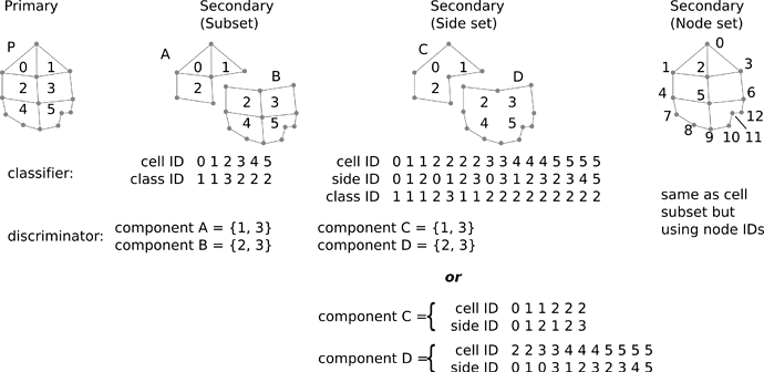
We are considering potential changes to smtk::geometry::Resource and SMTK’s VTK+PV extensions to express node sets, side sets, and element sets as indicator functions (for more compact storage than aeva’s approach).
Problem statement
Currently, several sessions that deal with discretized geometric models (i.e., meshes as models) create a separate VTK dataset for each component, even when that component is a subset of primitives from a primary (or referenced) component. This works well for small models, but as model sizes increase it becomes infeasible.
We also wish to handle the use case where users make selections or other references to parametric geometric models (i.e., CAD B-Rep spline models). The crux of the problem is how to efficiently expose geometry that in some cases is primary and in other cases is a reference to some primary geometry.
There are two primary tasks that any changes must accomplish:
- Allow any component to represent point-sets that are submanifolds of some other component’s point-set.
- Provide a method to render and interact with the point-set using SMTK’s VTK and ParaView extensions.
a. Rendering will require information specific to the indicator’s domain and may require backend-specific data as well.
b. Interactions include: picking, changing visibility, changing coloring, and potentially other visual style in response to user input such as hovering. It will also include drawing on primary components to edit the indicator map of a secondary component.
Proposed design
We propose adding the concept of indicator functions to smtk::geometry::Manager. Indicator functions are boolean functions
that map members g of some set G (point-sets such as primitive shapes in our case) to boolean values. If a primitive is mapped to true/1, it is selected by the indicator for rendering; if false/0, it is omitted from rendering.
Note that indicator functions as defined above may have different notions of their domain, but the range is always \left\{0, 1\right\} . Our proposed design would mirror this by allowing C++ classes freedom in choosing how the primary component is referenced by a particular IndicatorFunction class. Unlike the formal definition of an indicator function above, we will add a degree of freedom to indicators by making them a composition of maps. For some component A, its indicator is
where
- g is a geometric point-set associated with a primary component (and implemented as a backend-specific geometric object specified by UUID);
- c: G\rightarrow {\mathbb I} is a classifier that maps any g\in G to an integer value (i.e., a class); and
- d_A: {\mathbb I} \rightarrow \{0, 1\} is a discriminator that maps integer values in the range of f to a boolean value specific to component A (i.e., it chooses which geometric classes define the shape of A).
Specifying indicator functions for components as a discriminator composed with a classifer allows a classifier c to be shared by many components in a way that enforces constraints on the set of primary components.
Example
For example, consider a simulation code that expects material properties to be defined on volumes and boundary conditions on surfaces. If we create a component for each material and a component for each boundary condition, then it is best if materials have one classifier whose domain consists only of geometric data associated with volumetric cells and boundary conditions have a separate classifier whose domain consists only of geometric data associated with surface cells. By constraining the domain of the classifiers for materials and boundary conditions, we (1) prevent user errors in defining the geometry of secondary-geometry components and (2) accelerate rendering updates by limiting the input datasets that a given discriminator must be applied to. ![]()
What follows is a discussion of how the concepts above might apply to the two broad categories of geometric models that SMTK supports. Although the discussion below assumes VTK data is used for components, that is not a requirement of the design – it just simplifies the discussion.
Discrete geometry
With discrete geometric models, each primary component has a VTK dataset associated with it. The dataset’s primitives exactly define the model geometry. We will assume subsets, side sets, and node sets refer to these primitives and their boundaries (and only primitives and their boundaries – no secondary component can have geometry that splits a primary-component primitive into pieces).
Element sets
For element sets (subsets), a classifier used to define indicator functions for can be stored as an integer-valued cell-data array and the discriminator for a component is simply a set of integers for which d_A = 1 (all other integers have d_A = 0), as shown on the left in the figure below:
Side sets
For side sets, this is more complicated since a single primitive typically has multiple sides and each can be referenced individually by different components. We propose two schemes for indicator functions of side sets:
- The top of the 3rd column in the figure above would store 3 arrays for the classifier (cell ID, side ID, and the class corresponding to the given side of the given cell). Then, the discriminator would take the same form as subsets: a set of integer classes for which d_A = 1.
- The bottom of the 3rd column in the figure above illustrates an alternative scheme where each secondary component would store cell-ID and side-ID arrays (effectively collapsing c and d_A). Implicitly, the indicator function is 1 for all the enumerate sides and 0 for any side not referenced.
A complication of side sets is that they are generally not unique specifications; where a side is shared by multiple cells, it can be referenced with multiple, different (cell ID, side ID) tuples. For example, in the figure above, (cell 1, side 1) and (cell 3, side 0) refer to the same edge (the one shared by cell 1 and 3). If users create side sets by drawing on a geometric model, they may create side sets that need changes in order to meet constraints imposed by indicator functions. Continuing the example above, if component A and B in the second column of the figure represent regions with different materials, boundary conditions on components C and D in the third column may be required to be sides of a particular material (i.e., the BC may need to apply to (cell 1, side 1) rather than (cell 3, side 0) even though the user created the side set by drawing on cell 3).
Node sets
Finally, for node sets, we can use the same scheme as element sets above, but with the class array centered on points instead of cells.
Parametric geometry
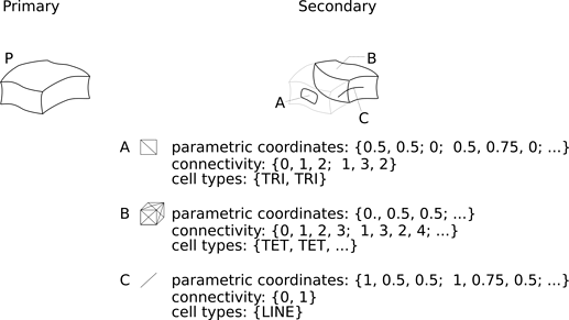
For CAD models or other sessions with parametric spline geometry, indicator functions can be expressed as geometric cell-primitives whose domain is the parameter-space of the primary component’s associated geometric data. In CAD parlance, the indicator function is a trimming curve (or surface or volume), as shown below:
Unlike discrete geometry, the difference between element sets, side sets, and node sets is simply the dimension of the cells expressing the trimmed geometry.
This gets complicated if (for example) a side set trims multiple face cells that each have a different parameterization. In general, the indicator function would be stored as cells grouped by the primary-component whose parameter-space they exist inside.
As with the discrete case, it may sometimes be useful to consider indicator functions defined as a discriminator composed with a classifier. In this case,
- the classifier would be a mesh partitioning the parameter spaces of some set of primary components, plus an integer-valued cell-data array assigning a class to each cell; and
- the discriminator would be a set of integer class-IDs for each secondary component.
This scheme would allow applications to enforce cases where secondary components must form a partition their primary components (e.g., displacement boundary conditions must never overlap and may sometimes be required to be specified over the entire boundary). It would also save storage compared to the case where secondary components store parameter-space meshes independently of one another. However, it would add geometric complexity in the event that secondary components are allowed to overlap one another arbitrarily, since the shared mesh would have to faithfully discretize all secondary components at once.
Implementation
This section covers how SMTK would implement the design above.
- We would extend the
smtk::geometry::Managerto provide access to a set of registered indicator function types and instances of those types.- Extensions that currently use
smtk::geometry::Geometrywould continue to fetch backend-specific data for rendering, but they would also need a way to get a list of components with indicators and expose them as well. - The descriptive phrase visibility badge would need to be updated to deal with components that have indicator functions and not primary geometry.
- Extensions that currently use
- Backends (such as the VTK backend) would register objects that other SMTK extensions can find in order to control the display of primary and secondary geometry.
- Note that because secondary geometry is coincident with primary geometry and potentially with other secondary geometry (if their sets overlap: d_A\bigcap d_B \neq \emptyset), applications will typically have to limit rendering to either primary components, secondary components, a subset of secondary components (e.g., only thermal boundary conditions), or even a single secondary component at a time).
- The control object would let applications introspect available rendering and picking options as well as choose which one should be active given the task at hand.
- Besides rendering, picking will have to be updated. Generally, picking should follow rendering (i.e., the things you can pick are the things being rendered), except that with secondary geometry what is actually being rendered is the primary geometry. Picked cells/points will thus always correspond to the primary geometry and must – depending on the selection mode – be mapped to the appropriate secondary geometry. This will require changes to
SelectionFootprintqueries andSelectionResponderoperations registered to resources supporting element/side/node-sets. - There are several avenues for how SMTK’s ParaView and VTK extensions might implement rendering and picking. These will be discussed in a separate topic on the VTK discourse site.

