Reactor modeling capability is introduced into SMTK2 and CMB5. Since now SMTK3&CMB6 should be released anytime soon, this topic is targeted to discuss the functionality and limitation of current rgg(AKA reactor geometry generator) session and future work on the reactor modeling. Simulation workflow and execution on HPC systems should be discussed in another post.
Current RGG session in SMTK2 and CMB5
- Able to model various pins, duct structures, sub-assemblies and a reactor core in the Simulation Model ToolKit (SMTK) and demonstrated using the Computational Model Builder (CMB)’s ModelBuilder Application.
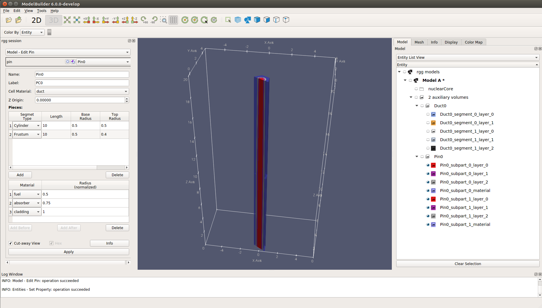
Figure1. defining a cross-section of the pin including the optional cell material surrounding it using the pin editor.
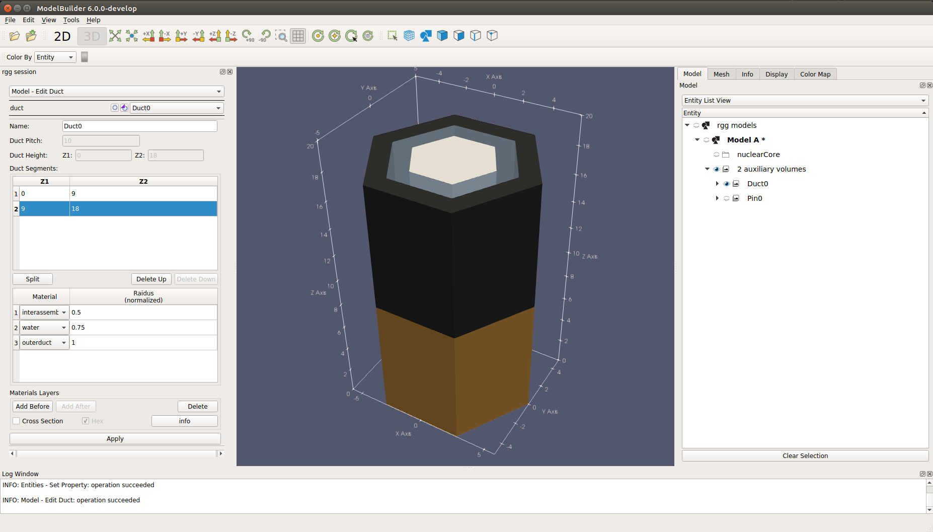
Figure2. defining a sub-assembly duct using the Duct Editor.
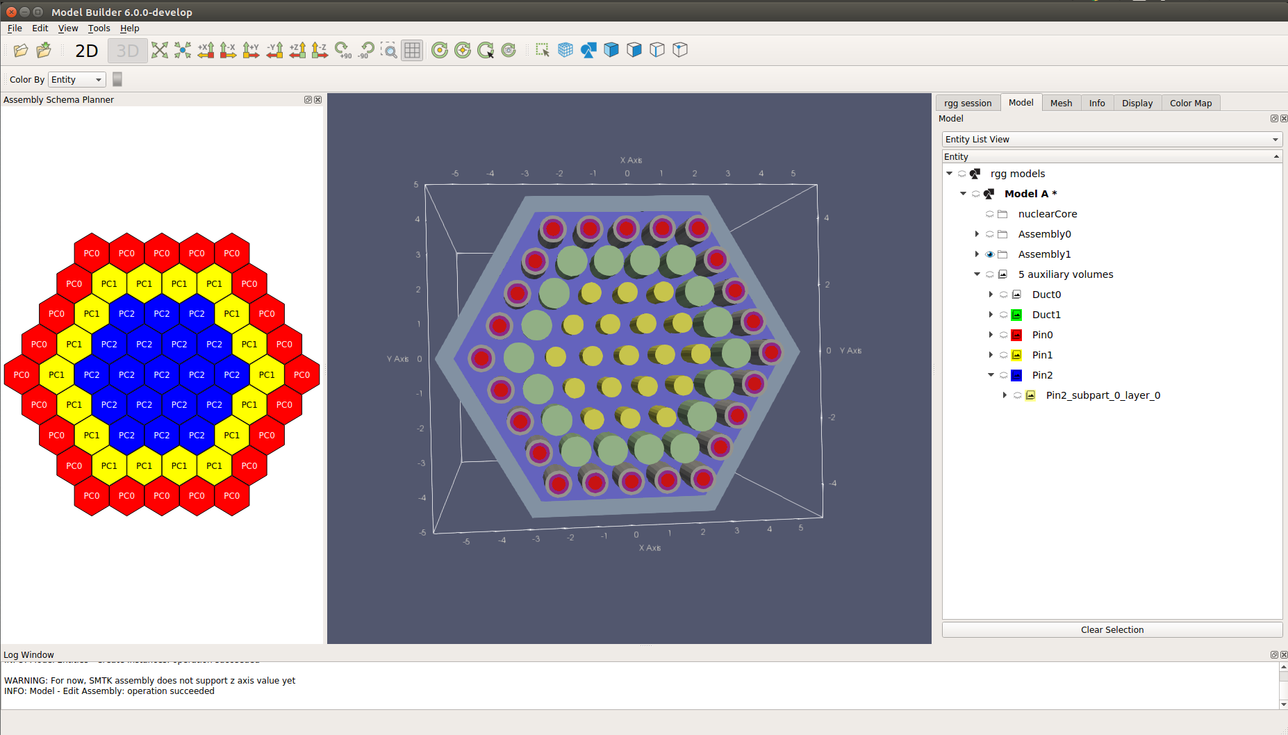
Figure3. a 2D schematic editor and a 3D view of an assembly looking down the z axis
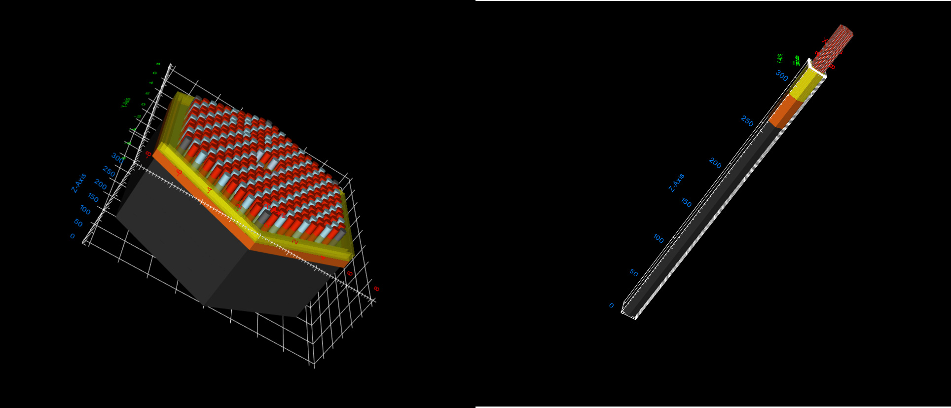
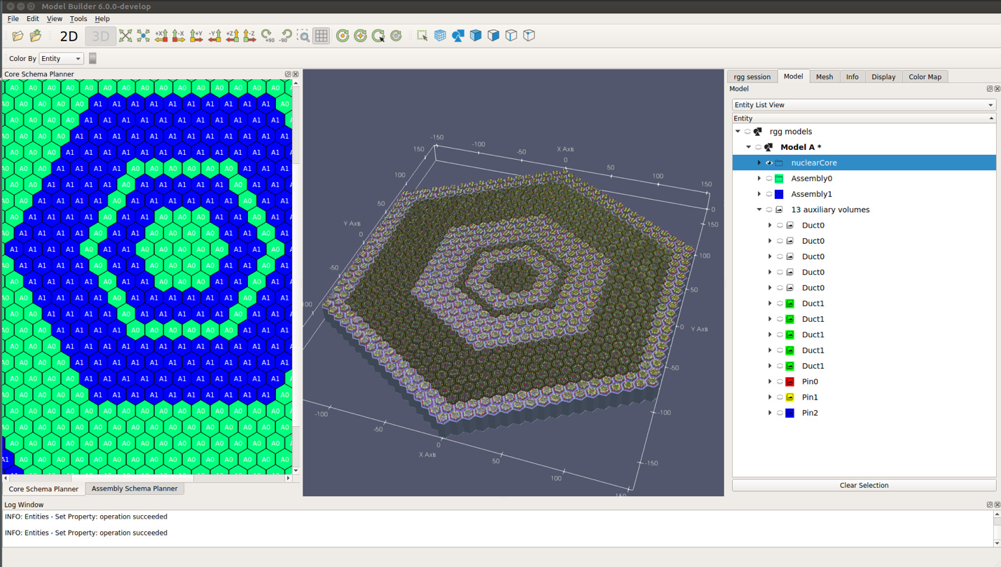
Figure4. a complex example reactor consisting of 919 sub-assemblies and over 56,000 pins - Able to define materials which fit PyARC specification.
- Able to read a reactor in rxf file format(a native file format for RGGNulcear application)
- Able to export a reactor in son file format(Standard Object Notation) and smtk file format(native smtk file format)
- Able to handle complex reactors which contain half a million of glpyhs.
TODO list in SMTK3 and CMB6
- RGG session should have its own descriptive phase generator other than using the generic tree view which lists all sub components. Below is a possible tree view.
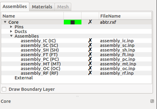
Figure5. a sample tree view for the nuclear core - Given the fact that nuclear pins are long thin cylinders, a z scale slider should be provided to let users adjust the comparative height.
Figure6. on right hand side is a sample assembly and on left hand side is a sample assembly whose z value is scaled to provide a clear view - Assembly/core schematic editor should provide rich methods to plan the layout for pins/assemblies such as(layout items via ring/circle/diangle).
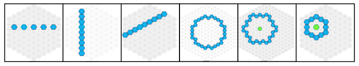
Figure 7. example of possible smart layout tools - Current nuclear modeling uses pin&duct-centric paradigm to meet customer’s needs. We should provide a layer-centric paradigm to meet other customer’s specification.
- Incomplete/missing features
- Modification of a nuclear pin&duct&assembly should propagate downstream. Currently
if a user modifies a pin, he/she needs to manually call apply on all rgg entities(assembly and core) which relies on this pin. - generate a vessel for the reactor
- filter the visibility of rgg entities via material(Ex. a user only wants to see parts whose material are sodium)
- add unit tests for all rgg operations
- Instead of breaking a rgg entity to sub layers and glyph the entity at layer level
(Ex. If a nuclear pin consists of two cylinders, then the glyph representation of this pin
actually contains two glyphs), it should be glyphed as a whole. SMTK2 is not able
to do so because it cannot specify colors for sub-blocks in a vtkMultiBlockDataset.
- Modification of a nuclear pin&duct&assembly should propagate downstream. Currently