I am looking at extending the SMTK Project Manager capabilities to support multiple interdependent simulations. I foresee this requiring development in three main areas:
-
Update the project plugin to provide a user interface for configuring projects with multiple attribute resources. (The current plugin is limited to one attribute resource.)
-
Update the SMTK core project to store and manage simulation job data.
-
Update the plugin to extend export operators for multiple simulation jobs.
This post discusses item 1, a user interface for project configuration. Depending on the response/feedback, I hope to follow these with posts discussing the other items.
Basic Approach
The proposed revisions will implement a limited subset of the planned workflow modeling capabilities from the SMTK roadmap. The plan is to use separate attribute resources to specify multiple simulations within a project. This will be more general and flexible than modeling multiple simulations in a single attribute resource, and is expected to be easier to implement as well.
With the proposed changes, each time a simulation job is submitted, job status and other metadata are saved in the project, including the filesystem location of the results on the remote system. This will allow the project manager to combine simulations specified by their attribute resource in the project.
For the first implementation, the plan is to integrate the new functionality as an advanced feature accessed from the project menu, and leave the current project functionality as-is.
UI Requirements and Mockup
For the new project configuration view, the basic user requirement is to specify one or more analyses, each modeled by an attribute resource and one or more geometric models. For the baseline use case, analyses are carried out by long-duration computing processes typically on HPC or other remote computing systems.
A mockup of the proposed UI panel shows two parts for configuring analyses and models, respectively.
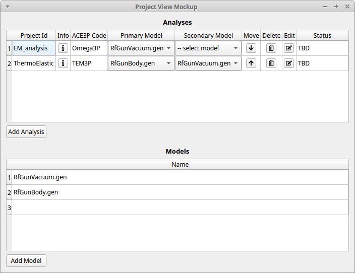
Analyses Table
The upper part of the view is a table for analysis specifications, with each row representing one attribute resource.
-
The “Project Id” column contains a string used to identify each attribute resource. This might be the resource name, but it will also be used as part of the folder name for storing analysis and job data on both desktop and remote systems. (We might, for example, display the resource name and internally use a slugified version.)
-
I included an “Info” column with tool button as a way for users to store some descriptive information, in a tooltip and/or popup window.
-
The “ACE3P Code” column is premature to include right now, because it would require some TBD interaction between the simulation plugin and the project plugin. It would nonetheless be handy to know what simulation code is specified by each attribute resource.
-
The “Primary Model” displays a combo box for selecting one of the model resources in the project. Minor point: the name that is displayed is the native model (not the resource name).
-
The “Secondary Model” is also a combo box. Note that no secondary model is selected in the first row of the table. Both models are optional, though you cannot assign a secondary model unless a primary model has been assigned.
-
The “Move” column has tool buttons to move rows up and down in the list. The order in the table implies the order of execution if/when multiple simulations are submitted together. This is analogous to a workflow sequential task.
-
The “Delete” column is for removing attribute resources from the project. Probably includes a confirmation dialog (“are you sure?”).
-
The “Edit” column has a toolbar to assign the attribute resource to the Attribute View tab. This is equivalent to selecting the attribute resource in the resource panel then raising the attribute editor to the front.
-
The “Status” column is still a work in progress. The baseline is to indicate the status of the current/latest simulation job; it might evolve into the more generate workflow “task state”. For jobs that are complete, an icon would/should be provided to begin visualization.
Models Table
As for the list of models, we might add a description field for some user-defined notes. Not shown in the mockup is a column for removing models from the project.
Additional Background
We have been using the project plugin at SLAC and LANL for over a year to model simulation problems computed by ACE3P and Truchas. In terms of user interface, the current plugin only presents a menu and a couple pop-up dialogs for configuring new projects and export. Each project contains a single attribute resource and up to two model resources. That is sufficient for many use cases, but at SLAC, there are a number of analyses where two simulations are loosely coupled, typically with an electromagnetic simulation supplying input data to an elastic/thermal simulation. There is an analogous use case with Truchas, which is used in conjunction with a view factor analysis code called Genre. To support these relatively simple, multiple-simulation projects, I want to begin implementing parts of the SMTK workflow modeling features that have been discussed in the past. This post begins documenting one approach toward that end.